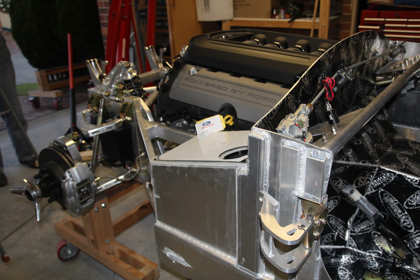
As mentioned at the end of my last post, the started motor has proved to be quite troublesome.
Prior to installing the engine I fitted the starter motor and then tried to lower the engine into the chassis and it became quite obvious that the starter was going to foul up on the foot box so we lifted the engine and removed the starter. Once we went through all the drama of getting the engine to sit right, I tried to reinstall the starter motor again and noticed that there was at least 20mm interference between the solenoid and the foot box. it would not even come close to lining up with the mounting holes.
At this point I new that another solution needed to be found so I jumped on the web and started to search for starter motors and googling clearance problems until I came upon a forum discussing rotating starters which I had heard of before. There were a few to choose from and I came across a starter specifically designed for the Coyote engine when it is being used in hot rods and areas where clearance is a problem so, doing some research and checking dimensions I reckoned this is the unit for me. The starter is a Power Master 9532 and has the added benefit of not being effected by heat which I was concerned about and that it has the capacity to crank engines up to 18:1 compression ratio. With the Coyote being 11:1 which is quite high, this starter should have no problems cranking over so I ordered one through Car Shop Inc in Illinois USA.
Once I received the starter motor I worked out how it works and started to set it in the correct orientation for my situation. From the moment I tried to mount it I new I was in trouble. To get the right orientation, the body of the starter had to be rotated to the bottom which in turn fouled up on webbing on the engine block and to rotate it upwards fouled on the foot box just like the previous one I had.
After quite a bit of jiggling about, I could see the point on the block where the starter was hitting so with the help of a mates reciprocating saw, I cut a portion of the webbing out and the starter slide right in. The black lines are the cut lines in the pics below and you can see the lack of clearanceThe next issue I faced was the lack of clearance to get a socket on the bolts as the orientation of the starter had the wiring connections in line with one of the bolts and the solonoid in line with another but we got one right, at least that was 33% correct. There was v ery little clearance between the body of the motor and the bolt head and getting a socket on was almost impossible so I ground down a cheap socket but still needed more clearance. After a bit of thought, I just went and got in hex bolts and made up a hex drive with 40cm of extensions and the job was dome.
When the engine was first fitted I noticed that the oil pan sat 35mm below the floor level of the car and this was to be expected as the standard Coyote oil pan is quite deep. When I ordered the new starter, I also ordered a Canton Low Profile Oil Pan to fix this issue.
My next post will have the fitting of the Canton pan so until then, see you next time.
Cheers
Russell
Friday, 14 August 2015
Thursday, 13 August 2015
Continuing to Move Forward
I had previously fitted all the braided stainless fuel lines right through out the car including the return lines into the fuel tank. As the lines into the tank are quite exposed, an aluminium skid plate was made to provide protection for the lines and tank against spraging up on kerbing or speed humps etc. The last thing I would want is to rip the lines out of the tank, not that it would happen but a skid plate is a handy precaution in any case.
To keep things relative cool and to have fresh air flowing around the cock pit, I fitted fresh air vents that fit above the foot well and have a slide arrangement for opening and closing the vent. These were very easy to fit but a problem is pending as the alignment between the holes for the 70mm fresh air hose in the chassis and the vent holes misalign by 20mm or more. I can see how to rectify this but will require a little bit of surgery to the vent hole. My die grinder and an aluminium cut rotary bit will fix this.(pic to come)
With the Coyote engine, I brought in the complete Ford Racing wiring harness and ECU which also had a drive by wire accelerator pedal and electronics. This is where I come to the point of my incompetence, I know nothing about electronics or electrical issues for that matter. Changing the battery in a smoke alarm tests my electrical knowledge. Anyway, I have this plastic accelerator pedal that I have been looking at for a long time wondering how to fit it. I have seen the LS Chev stuff using a series of push rods and bell cranks and wondered how to make this work in my situation. It's funny that having seen the Chev set up and trying to work around this system that I couldn't see what was before me. This was one of those situations where I had a mid night epiphany and the solution fell into place...why use push rods and bell cranks to fit the unit where it shouldn't be, why not just bolt it to the fire wall and modify the pedal to hide behind the Tilton pedal I wanted to use...so I did. I cut the pedal off the Ford unit and made a crank to operate from the Tilton pedal to the Ford Racing pedal.
Once the Ford pedal was cut down, I did a trial fit and decided to cut the bosses from the back of the mount to allow more clearance.
When I had established the correct location for the pedal, I set about making a pedal extension and push rod to connect the Tilton pedal to the Ford pedal. I have made provision to include bronze self lubricating bushes to avoid friction between the metal on metal push rod clevises and extension. The pedal extension had to veer back toward the fire wall to almost a vertical position to give the required clearance and to allow the correct amount of movement to ensure that the Ford pedal maintained full operation and also tweeked to maintain vertical alignment with the Tilton pedal.
Once I was satisfied that the pedal would work ok, I drilled all the holes and bolted every thing together. A real bonus was the Tilton pedal had a series of 5 holes which allowed adjustment for my push rod so the optimum arc was achieved with out much drama, almost as if they new someone would do this.
Once fully installed, the Ford drive by wire mechanism is well hidden and can't be seen unless someone wants to make a point of finding it.
Well, that's all for tonight. I really enjoy solving all the little issues associated with building hot rods and speciality cars. In the next episode I have a real conundrum,the starter motor doesn't come anywhere close to fitting.
Cheers
Russell
To keep things relative cool and to have fresh air flowing around the cock pit, I fitted fresh air vents that fit above the foot well and have a slide arrangement for opening and closing the vent. These were very easy to fit but a problem is pending as the alignment between the holes for the 70mm fresh air hose in the chassis and the vent holes misalign by 20mm or more. I can see how to rectify this but will require a little bit of surgery to the vent hole. My die grinder and an aluminium cut rotary bit will fix this.(pic to come)
With the Coyote engine, I brought in the complete Ford Racing wiring harness and ECU which also had a drive by wire accelerator pedal and electronics. This is where I come to the point of my incompetence, I know nothing about electronics or electrical issues for that matter. Changing the battery in a smoke alarm tests my electrical knowledge. Anyway, I have this plastic accelerator pedal that I have been looking at for a long time wondering how to fit it. I have seen the LS Chev stuff using a series of push rods and bell cranks and wondered how to make this work in my situation. It's funny that having seen the Chev set up and trying to work around this system that I couldn't see what was before me. This was one of those situations where I had a mid night epiphany and the solution fell into place...why use push rods and bell cranks to fit the unit where it shouldn't be, why not just bolt it to the fire wall and modify the pedal to hide behind the Tilton pedal I wanted to use...so I did. I cut the pedal off the Ford unit and made a crank to operate from the Tilton pedal to the Ford Racing pedal.
Once the Ford pedal was cut down, I did a trial fit and decided to cut the bosses from the back of the mount to allow more clearance.
When I had established the correct location for the pedal, I set about making a pedal extension and push rod to connect the Tilton pedal to the Ford pedal. I have made provision to include bronze self lubricating bushes to avoid friction between the metal on metal push rod clevises and extension. The pedal extension had to veer back toward the fire wall to almost a vertical position to give the required clearance and to allow the correct amount of movement to ensure that the Ford pedal maintained full operation and also tweeked to maintain vertical alignment with the Tilton pedal.
Once I was satisfied that the pedal would work ok, I drilled all the holes and bolted every thing together. A real bonus was the Tilton pedal had a series of 5 holes which allowed adjustment for my push rod so the optimum arc was achieved with out much drama, almost as if they new someone would do this.
Once fully installed, the Ford drive by wire mechanism is well hidden and can't be seen unless someone wants to make a point of finding it.
Well, that's all for tonight. I really enjoy solving all the little issues associated with building hot rods and speciality cars. In the next episode I have a real conundrum,the starter motor doesn't come anywhere close to fitting.
Cheers
Russell
Sunday, 9 August 2015
Life Is Not Meant To Be Easy.
Once the engine was fully fitted and the tranny mounts in place, The clearance issue with the bell housing came into play. The bell housing starter opening was resting on the stainless steel heat shield which is not an ideal situation but as I could depress the heat shield I opted to just put an insulator between the bell housing and the shield as removing the engine is such a major task. The trouble is, the more I thought about this solution the less I liked it so on Saturday,the engine came out again and the bell housing ground 6mm to provide clearance.
One of the things I had not thought about prior to removing the engine was the solid stainless fuel line that exited low down in the transmission tunnel and as it turns out, was totally inaccessible with the engine in place. With the engine out of the chassis I attached a stainless fuel line and clamped in position so I can fit it to the fuel rails.Thank goodness I thought of this as the engine would have to come out again when we try to fit the fuel lines, you have to have a win occasionaly
We then attempted to refit the engine which with all the knowledge we now had, it fitted with a minimal of fuss as far as this thing would allow or maybe we just expect the unexpected. We had learned to balance the engine dead level on the hoist as it would sit in it's final position, we had a lever to twist the engine as it was lowered and we knew to bolt the chassis mounts to the block mounts and lever the mounts into place, as a matter of fact, we were getting pretty good at this.
With the engine in place I proceeded to fit the Boss Alternator Kit which came with all the brackets, belt and tensioner. The tensioner had me beat for a while as when I went to draw the tensioner in to fit the serpentine belt it would not move, ok, what now. After looking at it for a while and posting on the Cobra Forums about the problem and getting plenty of replies about the orientation of the belt which I knew, I grabbed a breaker bar and socket and gave it an almighty heave to which it responded with a bit of a jolt and came forward so smoothly and with plenty of tension The problem turned out to be that during the tensioner assembly process the nylon membrane had got wedged between the moving parts and caused resistence and me not wanting to heavy hand it didn't overcome the resistence, however a breaker bar did and it now works a treat.
To get the gear lever in the right position, I got a Pro-5.0 center shifter and after cutting an inspection hole in the trans tunnel I fitted the shifter and grabbed all gears immediately which surprised me with a stationary engine. The center shifter came with shift locks to prevent over shifting on those ham fisted gear shifts but this provision was so bulky and would not allow the rubber boot to go over it so I consulted Mr Google and he informed me that the TKO-600 transmission had built in shift locks and recommended not using the after market type so half an hour in the lathe and they were gone.and this is the finishes item.
Another job that was done was to fit the fuel level sensor into the fuel tank which presented it's own set of issues, namely, how do you drill a 25mm hole in the fuel tank and not get the ingress of aluminium shavings in the tank, No big deal, just tape an extension to a vacume cleaner, position it under the cut line and go for it. Thanks to Guy Elliott for this little tip.
I was able to run the vacuum extension around the base of the tank and am satisfied that all shavings have been vacuumed up.
That's all for today
See you next time
Cheers Russell.
One of the things I had not thought about prior to removing the engine was the solid stainless fuel line that exited low down in the transmission tunnel and as it turns out, was totally inaccessible with the engine in place. With the engine out of the chassis I attached a stainless fuel line and clamped in position so I can fit it to the fuel rails.Thank goodness I thought of this as the engine would have to come out again when we try to fit the fuel lines, you have to have a win occasionaly
We then attempted to refit the engine which with all the knowledge we now had, it fitted with a minimal of fuss as far as this thing would allow or maybe we just expect the unexpected. We had learned to balance the engine dead level on the hoist as it would sit in it's final position, we had a lever to twist the engine as it was lowered and we knew to bolt the chassis mounts to the block mounts and lever the mounts into place, as a matter of fact, we were getting pretty good at this.
With the engine in place I proceeded to fit the Boss Alternator Kit which came with all the brackets, belt and tensioner. The tensioner had me beat for a while as when I went to draw the tensioner in to fit the serpentine belt it would not move, ok, what now. After looking at it for a while and posting on the Cobra Forums about the problem and getting plenty of replies about the orientation of the belt which I knew, I grabbed a breaker bar and socket and gave it an almighty heave to which it responded with a bit of a jolt and came forward so smoothly and with plenty of tension The problem turned out to be that during the tensioner assembly process the nylon membrane had got wedged between the moving parts and caused resistence and me not wanting to heavy hand it didn't overcome the resistence, however a breaker bar did and it now works a treat.
To get the gear lever in the right position, I got a Pro-5.0 center shifter and after cutting an inspection hole in the trans tunnel I fitted the shifter and grabbed all gears immediately which surprised me with a stationary engine. The center shifter came with shift locks to prevent over shifting on those ham fisted gear shifts but this provision was so bulky and would not allow the rubber boot to go over it so I consulted Mr Google and he informed me that the TKO-600 transmission had built in shift locks and recommended not using the after market type so half an hour in the lathe and they were gone.and this is the finishes item.
Another job that was done was to fit the fuel level sensor into the fuel tank which presented it's own set of issues, namely, how do you drill a 25mm hole in the fuel tank and not get the ingress of aluminium shavings in the tank, No big deal, just tape an extension to a vacume cleaner, position it under the cut line and go for it. Thanks to Guy Elliott for this little tip.
I was able to run the vacuum extension around the base of the tank and am satisfied that all shavings have been vacuumed up.
That's all for today
See you next time
Cheers Russell.
Monday, 22 June 2015
A New Milestone Has Been Reached
With the engine, trans, clutch and bell housing cluttering up my limited space, it was time to put the lot together and get it in the car.
First thing I did was to remove the flywheel and fit the block plate. To do this I had to relieve the central bore of the block plate to clear the crank sensor ring so it would sit flat on the block face.

Once the block plate is on the dowels and sitting flat on the face of the block, the bell housing can be fitted. In this case I am using a QuickTime RM-6081 that carries an SFI 6.1 safety rating. The bell housing can then be mounted to the engine and the bolts torqued to the correct spec. This is where disaster struck. When working with anything made from aluminium I am very cautious of the loads being put on bolts. I took the bolts supplied with the bell housing and screwed them into the holes just to be sure and they screwed in nice and firm. The specified torque for the bolts was 47Nm so I set my torque wrench at 20Nm for the initial tightening sequence. I nipped each thread to a snug torque then started to apply the load. I had only applied a light load (less than the set 20Nm) when the bolt felt very plastic which I thought was odd so I moved to another bolt and the same thing happened. That is where I should have investigated further but I tried another bolt and once again the bolt went dead. I removed a bolt and measured the diameter and pitch which was 3/8"UNC then went to the internet and googled the Coyote/QuickTime combination and their were several posts warning about this very situation, the threads in the block were in fact 10mm x 1.5 which means the 3/8" thread was 1/2mm smaller and the thread was coarser and when I tried the bolts the coarse thread took up any clearance and made it feel like all was ok and I had very effectively stripped 3 bolt holes, oh bugger, what now. The bosses in which the mounting holes were tapped into are quite a deal longer than the threads, that is, the threads were less than half the way through the boss so I got the correct tap and ran the thread all the way through and fitted much longer bolts, presto, job done.
Having got the bell housing correctly torqued up I set a dial indicator and clocked up the bore of the housing as this has to be with in a total run out error of .010" or .005" of the centre line of crank and gearbox shaft.
I found with my bell housing that it had a significant error of .014 total indicator run out but a bit jiggling around and I was able to repeat the reading that were with in the allowed error so I decided that I had it right.
Next step was to fit the clutch which wasn't a big deal. I has purchased a clutch pin kit for this 11" Ram Performance clutch so I had to remove the flywheel again and press the standard pins out and fit the stepped pins from the pin kit.
The next step was to fit the bell housing to the gear box. The QuickTime bell housing comes with a close tolerance centering ring to align the box to the bell housing and having fitted the ring it is just a matter of bolting the gear box and bell housing together.
As there is no room in the tranny tunnel to run a clutch throw out fork and slave cylinder, it is necessary to run a hydraulic throw out bearing instead. Having done some previous research, all roads pointed to Mal Wood Automotive in QLD who just happens to make a much improved unit. I contacted Mal and ordered the bearing and Mal also made the mods to the TKO bearing adaptor for me. This is a great unit and very easy to fit, it is just a matter of removing a mounting bolt and replacing it with a pin supplied to stop the bearing from turning. To set the distance for the bearing to pressure plate fingers, a series of conical spacers are provided and is only a matter of following Mals instructions for measurements and the jobs done.


One thing I had to do was to get a right angle fitting for the feed line so it would easily clear the opening in the bell housing. I could have got away with this but I thought for the sake of $25 I won't have to worry about the line rubbing on the bell housing opening. I then fitted the trans to the engine and it just fell together which is always good.

The time has come to fit the engine to the chassis which is an exciting time as so much time is spent getting ready for this moment. As Murphys law would have it, not all went to plan. Firstly, this is one heck of a big engine dimensionally with very little clearance in the engine compartment and is quit difficult to line everything up at the same time. I mounted the engine mounts to the chassis and the corresponding mounts to the engine then proceeded to lift the engine and trans into place. Without going into 4 hours of pushing and shoving and trying everything possible, this %$#@#*$ thing simply will not fit. We could not get the engine back far enough to align with the mounts. One of the critical issues is the engine has to be correctly aligned on the hoist and not tilted one side to the other as it is so wide that a small error creates a major problem trying to get it in the engine bay. We pulled the mounts of the chassis and dropped the engine as low as it would go with the view of coming up under the mounts and that is when we realised that the mounts would not fit regardless so we removed the engine and started taking measurements (which we should have done at the start). Their was a 38mm discrepancy between the block mounts and the chassis mounts so that ended our day. On Sunday morning I emailed Pace about the problem and about 10 minutes later I got a response from Craig, the owner of Pace saying he would have a look at the problem on the next day. Around midday I got an email from Pace saying they had built new mounts and they were on their way to me, I received them Friday afternoon, what great service from Absolute Pace. You can see the difference in the pic
On Saturday morning I was going to have another go at fitting the engine but it was so cold in Geelong I decided that their are other things that need doing, only in the warm of the house. On Sunday my friend Deb said "lets go fit that engine" so we did. Beautiful sunny day, very cold but had the potential to warm to at least 8 degrees. On the previous day I had fitted the mounts and measured them and balanced the engine so it should be an easy fit. We dropped the engine into the chassis and started to jiggle and jack it around and that's when Noel, my neighbor came in and with the extra hand we worked out that the chassis mounts need to come off and we fitted them to the block mount and we were able to get the engine bolted in position.


The transmission mount has been bolted into position but I think the engine will have to come out again as the QuickTime bell housing (starter motor area)is contacting the drivers foot box so I reckon that if I grind 5mm of the bell housing all should be sweet.
Well stayed tuned for the next episode in my adventures and please contact me if you want more information.
Cheers
Russell
First thing I did was to remove the flywheel and fit the block plate. To do this I had to relieve the central bore of the block plate to clear the crank sensor ring so it would sit flat on the block face.
Once the block plate is on the dowels and sitting flat on the face of the block, the bell housing can be fitted. In this case I am using a QuickTime RM-6081 that carries an SFI 6.1 safety rating. The bell housing can then be mounted to the engine and the bolts torqued to the correct spec. This is where disaster struck. When working with anything made from aluminium I am very cautious of the loads being put on bolts. I took the bolts supplied with the bell housing and screwed them into the holes just to be sure and they screwed in nice and firm. The specified torque for the bolts was 47Nm so I set my torque wrench at 20Nm for the initial tightening sequence. I nipped each thread to a snug torque then started to apply the load. I had only applied a light load (less than the set 20Nm) when the bolt felt very plastic which I thought was odd so I moved to another bolt and the same thing happened. That is where I should have investigated further but I tried another bolt and once again the bolt went dead. I removed a bolt and measured the diameter and pitch which was 3/8"UNC then went to the internet and googled the Coyote/QuickTime combination and their were several posts warning about this very situation, the threads in the block were in fact 10mm x 1.5 which means the 3/8" thread was 1/2mm smaller and the thread was coarser and when I tried the bolts the coarse thread took up any clearance and made it feel like all was ok and I had very effectively stripped 3 bolt holes, oh bugger, what now. The bosses in which the mounting holes were tapped into are quite a deal longer than the threads, that is, the threads were less than half the way through the boss so I got the correct tap and ran the thread all the way through and fitted much longer bolts, presto, job done.
Having got the bell housing correctly torqued up I set a dial indicator and clocked up the bore of the housing as this has to be with in a total run out error of .010" or .005" of the centre line of crank and gearbox shaft.
I found with my bell housing that it had a significant error of .014 total indicator run out but a bit jiggling around and I was able to repeat the reading that were with in the allowed error so I decided that I had it right.
Next step was to fit the clutch which wasn't a big deal. I has purchased a clutch pin kit for this 11" Ram Performance clutch so I had to remove the flywheel again and press the standard pins out and fit the stepped pins from the pin kit.
The next step was to fit the bell housing to the gear box. The QuickTime bell housing comes with a close tolerance centering ring to align the box to the bell housing and having fitted the ring it is just a matter of bolting the gear box and bell housing together.
As there is no room in the tranny tunnel to run a clutch throw out fork and slave cylinder, it is necessary to run a hydraulic throw out bearing instead. Having done some previous research, all roads pointed to Mal Wood Automotive in QLD who just happens to make a much improved unit. I contacted Mal and ordered the bearing and Mal also made the mods to the TKO bearing adaptor for me. This is a great unit and very easy to fit, it is just a matter of removing a mounting bolt and replacing it with a pin supplied to stop the bearing from turning. To set the distance for the bearing to pressure plate fingers, a series of conical spacers are provided and is only a matter of following Mals instructions for measurements and the jobs done.
One thing I had to do was to get a right angle fitting for the feed line so it would easily clear the opening in the bell housing. I could have got away with this but I thought for the sake of $25 I won't have to worry about the line rubbing on the bell housing opening. I then fitted the trans to the engine and it just fell together which is always good.
The time has come to fit the engine to the chassis which is an exciting time as so much time is spent getting ready for this moment. As Murphys law would have it, not all went to plan. Firstly, this is one heck of a big engine dimensionally with very little clearance in the engine compartment and is quit difficult to line everything up at the same time. I mounted the engine mounts to the chassis and the corresponding mounts to the engine then proceeded to lift the engine and trans into place. Without going into 4 hours of pushing and shoving and trying everything possible, this %$#@#*$ thing simply will not fit. We could not get the engine back far enough to align with the mounts. One of the critical issues is the engine has to be correctly aligned on the hoist and not tilted one side to the other as it is so wide that a small error creates a major problem trying to get it in the engine bay. We pulled the mounts of the chassis and dropped the engine as low as it would go with the view of coming up under the mounts and that is when we realised that the mounts would not fit regardless so we removed the engine and started taking measurements (which we should have done at the start). Their was a 38mm discrepancy between the block mounts and the chassis mounts so that ended our day. On Sunday morning I emailed Pace about the problem and about 10 minutes later I got a response from Craig, the owner of Pace saying he would have a look at the problem on the next day. Around midday I got an email from Pace saying they had built new mounts and they were on their way to me, I received them Friday afternoon, what great service from Absolute Pace. You can see the difference in the pic
On Saturday morning I was going to have another go at fitting the engine but it was so cold in Geelong I decided that their are other things that need doing, only in the warm of the house. On Sunday my friend Deb said "lets go fit that engine" so we did. Beautiful sunny day, very cold but had the potential to warm to at least 8 degrees. On the previous day I had fitted the mounts and measured them and balanced the engine so it should be an easy fit. We dropped the engine into the chassis and started to jiggle and jack it around and that's when Noel, my neighbor came in and with the extra hand we worked out that the chassis mounts need to come off and we fitted them to the block mount and we were able to get the engine bolted in position.
The transmission mount has been bolted into position but I think the engine will have to come out again as the QuickTime bell housing (starter motor area)is contacting the drivers foot box so I reckon that if I grind 5mm of the bell housing all should be sweet.
Well stayed tuned for the next episode in my adventures and please contact me if you want more information.
Cheers
Russell
Subscribe to:
Posts (Atom)