Once the body was in place and bolted along the sills, I made sure that the body was sitting right then placed rivets along the boot lip area and the mounting tabs on the front and rear bulk heads. All the mounting points aligned perfectly which made the job easy however the body is 15mm off centre but this is the way it was originally fitted which I think is very poor as it was easy to get correctly aligned when initially fitting the body. Pace jig the body to maintain the profile which is good but no one was looking at how the body aligned with the chassis. I have some other issues with alignment that I will go through latter.
When I was satisfied that the mounts where as Pace fitted them, I removed the "4 x 2" that holds the body in place making it easy to move around and the lip that is moulded into the dash area and the rear bulk head.
I cut the lip with a plastic blade in my cordless Dremel and used a sanding disc to clean up the profile and smooth everything out as well as remove all the sharp edges.
Having got to this point I was able to fit the windscreen washers and demisters. I had pre-fitted these items prior to mounting the body as it is much easier to do.One of the things to watch out for when fitting the windscreen washers is the threaded section may not be long enough to get a nut on due to the thickness of the composite in the cowl area. In my case it was 8mm thick so I got out the trusty Dremel and a face mask and ground an area large enough for the nut and removed around 4mm of the thickness so the the washer can be securely fastened.I also changed the washer hose to a rubber type over the plastic as the one supplied has a serious kink in the wrong spot and the rubber was more pliable to weave though the areas that was required
I also installed the demisters that I had previously fitted while the body was on the trolley. Doing these things where you are clear of wiring etc makes it so much easier.
Time is slipping away tonight but I have so much to share in the next few installments so until then,
Cheers
Russell
Friday, 4 November 2016
Thursday, 14 July 2016
The Body Is Finally On
I thought fitting the body would be more difficult than it was and was quite surprised that it went on as easy as it did. I removed as many obstacles as I could like the radiator, fuel filler hose and rear infill panels. By removing the radiator it allows the front panels to be pulled in enough so the body mounting tabs can be slid into position.
I rounded up five extra guys to help and as Alan fell of his bike on the way to my place, he arrived looking like Dracula had a party on his face and legs but he wasn't going to miss the fun and became the designated photographer, a task he performed well. You really need five to lift and stretch the body over the door hinges and move it into place so the screws align with the original mounts, it worked out well.
From the time we picked the body up from the trolley to the time the last mounting bolt was in place was about 15 minutes.
Thanks to all those that helped and those that wished the project well, your support is invaluable.
Cheers
Russell
I rounded up five extra guys to help and as Alan fell of his bike on the way to my place, he arrived looking like Dracula had a party on his face and legs but he wasn't going to miss the fun and became the designated photographer, a task he performed well. You really need five to lift and stretch the body over the door hinges and move it into place so the screws align with the original mounts, it worked out well.
From the time we picked the body up from the trolley to the time the last mounting bolt was in place was about 15 minutes.
Thanks to all those that helped and those that wished the project well, your support is invaluable.
Cheers
Russell
Wednesday, 13 July 2016
Things Are Getting Exciting.
It has been some time since I last posted my progress and the reason for that is there really hasn't been a lot to write about. I have been doing a bit of travelling around but mainly needed to recharge the batterys but I am now getting back into it.
Having got the car home from the Auto Elec, I was able to have a good look over it and see the amount of work it takes to get the wiring into the right spot. The engine loom had to be split into four looms to feed it into the cockpit to mate up with the Ford Racing ECU loom and components and having very little space, this is quite a task
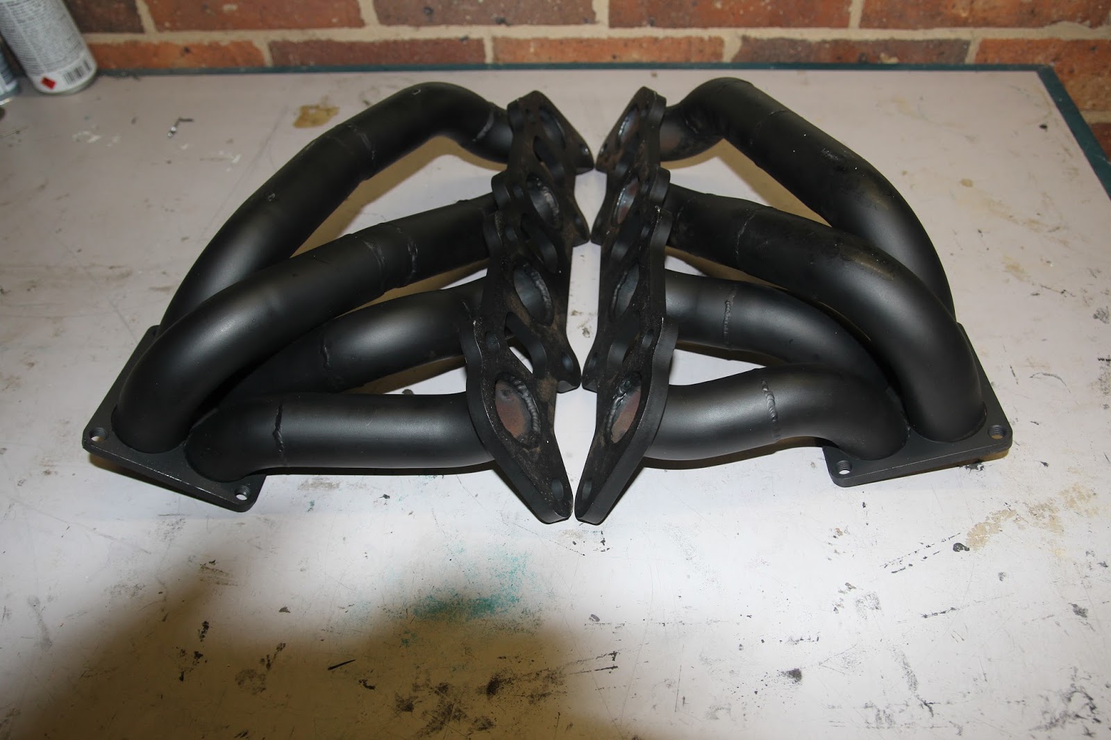
In my last post I showed the headers for this project. As was expected, they took a bit of fitting and I found out during the fitting process that they could be fitted to the engine while it was out of the car but as I has all the wiring in place I didn't want to pull the engine out completely.
To get the headers on, I had to move the engine forward 150mm. Fortunately for me we had enough slack in the loom to allow this so we just put a sling under the pulley and lifted the engine as high as it would go and juggled the headers until they went in. Getting the bolts in was a trick but we managed it. As you can see, it is very tight. No, that is not a V16, just reflection.
An interesting thing about the rear axle is the clips holding the stub axles into the diff. The ones supplied by Pace are too small in diameter and very much out of shape. Fortunately for me, Guy, Cam and I were refitting my gear box after repairing a severe leak in the hydraulic throw out bearing when Cam noticed my axles were dislocated, they had just pulled straight out of the diff. I was advised to get the genuine GM clips and that made all the difference, the axles snapped into place beautifully. For the sake of $23,anyone using the VF Commodore diff, make sure you have genuine clips or it could be nasty. The variation in the clips is evident in the pics.
Recieved the tail shaft a little while ago, haven't fitted it yet but what a solid piece it is. I can't see me ripping that out in a hurry.
I have decided to make my own working side pipes and so far have put together the merge collectors and made the flange gaskets. The merge collectors will run into a pair of 4" diameter 400CPSI Euro 4 catalytic converters then into the side pipes.
The collectors are on an angle so they align with the opening in the body. The collectors have just been tacked to the flange plates at this stage as provision will need to be made to the collector to allow spring washers to be fitted, this mean reforming the collector around the bolt holes. The gaskets have been made from a sheet of exhaust gasket material using the flanges as a guide. By just cutting the gasket material to size with tin snips then clamping between the two flange plate, drill the four mounting holes and bolt the flanges together. The bolts give a positive position to grip in a vice and then you can run a hole saw through the gasket. In this case the primary tube holes are 1-5/8". Once the drilling was done, I just cleaned everything up with a file.
The merge collectors are now fitted temporally so that when the body is fitted they can be properly aligned.Once again, the reflection plays tricks.
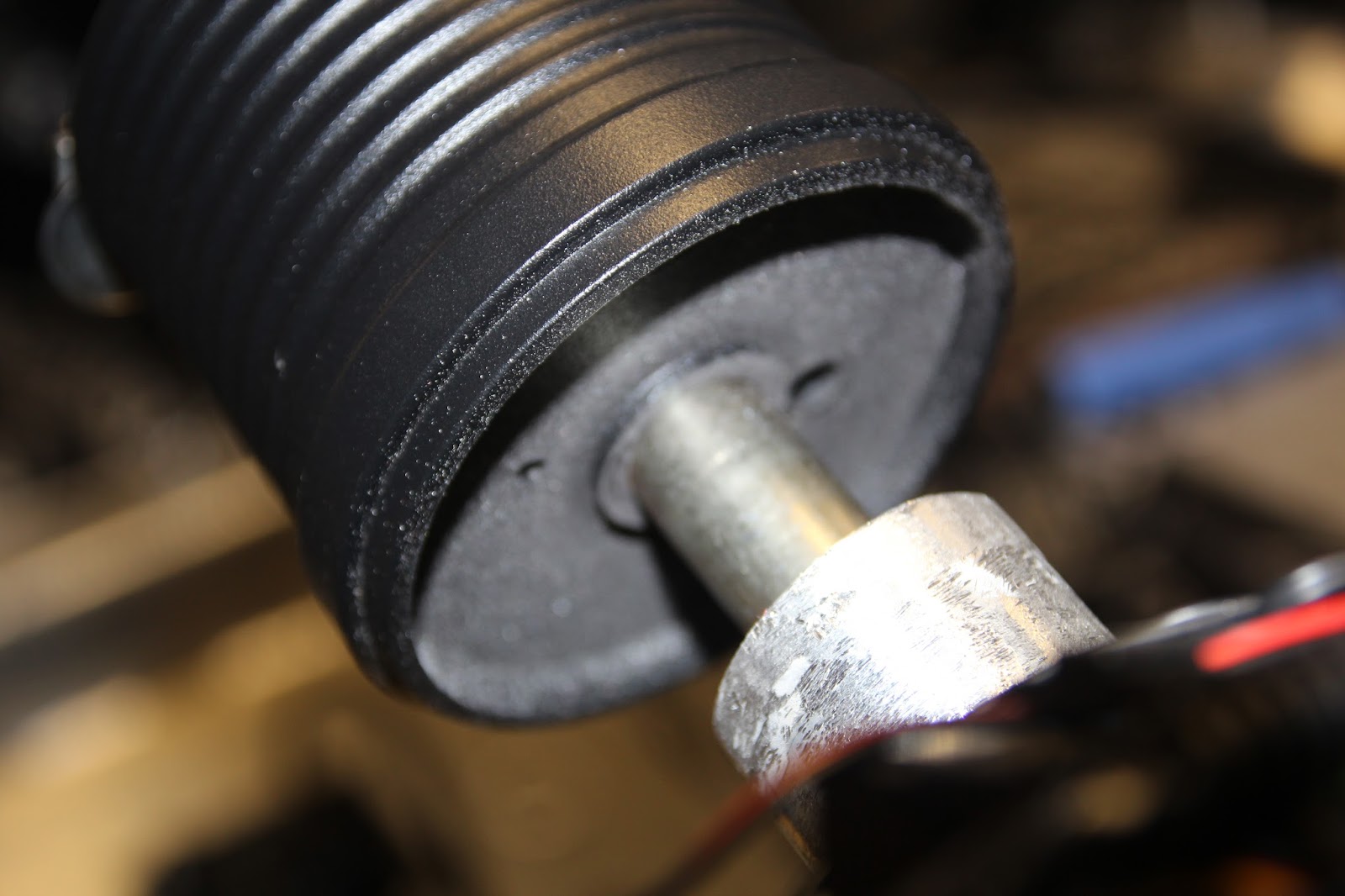
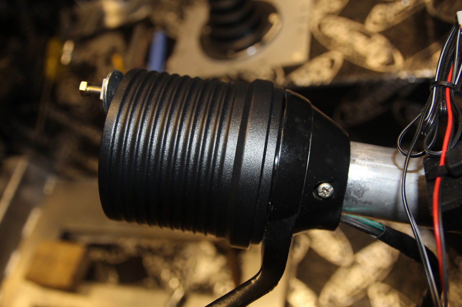
I had to shorten the steering column shroud about 16mm to allow the steering wheel hub to seat correctly on the steering shaft spline and taper and to allow the indicator stalk to sit into the dash. Having done this and having the indicator stalk in the right place, the steering wheel hub requires modification to get the internal taper and spline to fully seat. I did this with a rotory drill and sanding sleeve.
The body has now been fitted but I will post on that in a few days.
Till then Cheers
Russell
Having got the car home from the Auto Elec, I was able to have a good look over it and see the amount of work it takes to get the wiring into the right spot. The engine loom had to be split into four looms to feed it into the cockpit to mate up with the Ford Racing ECU loom and components and having very little space, this is quite a task
In my last post I showed the headers for this project. As was expected, they took a bit of fitting and I found out during the fitting process that they could be fitted to the engine while it was out of the car but as I has all the wiring in place I didn't want to pull the engine out completely.
To get the headers on, I had to move the engine forward 150mm. Fortunately for me we had enough slack in the loom to allow this so we just put a sling under the pulley and lifted the engine as high as it would go and juggled the headers until they went in. Getting the bolts in was a trick but we managed it. As you can see, it is very tight. No, that is not a V16, just reflection.
An interesting thing about the rear axle is the clips holding the stub axles into the diff. The ones supplied by Pace are too small in diameter and very much out of shape. Fortunately for me, Guy, Cam and I were refitting my gear box after repairing a severe leak in the hydraulic throw out bearing when Cam noticed my axles were dislocated, they had just pulled straight out of the diff. I was advised to get the genuine GM clips and that made all the difference, the axles snapped into place beautifully. For the sake of $23,anyone using the VF Commodore diff, make sure you have genuine clips or it could be nasty. The variation in the clips is evident in the pics.
Recieved the tail shaft a little while ago, haven't fitted it yet but what a solid piece it is. I can't see me ripping that out in a hurry.
I have decided to make my own working side pipes and so far have put together the merge collectors and made the flange gaskets. The merge collectors will run into a pair of 4" diameter 400CPSI Euro 4 catalytic converters then into the side pipes.
The collectors are on an angle so they align with the opening in the body. The collectors have just been tacked to the flange plates at this stage as provision will need to be made to the collector to allow spring washers to be fitted, this mean reforming the collector around the bolt holes. The gaskets have been made from a sheet of exhaust gasket material using the flanges as a guide. By just cutting the gasket material to size with tin snips then clamping between the two flange plate, drill the four mounting holes and bolt the flanges together. The bolts give a positive position to grip in a vice and then you can run a hole saw through the gasket. In this case the primary tube holes are 1-5/8". Once the drilling was done, I just cleaned everything up with a file.
The merge collectors are now fitted temporally so that when the body is fitted they can be properly aligned.Once again, the reflection plays tricks.
I had to shorten the steering column shroud about 16mm to allow the steering wheel hub to seat correctly on the steering shaft spline and taper and to allow the indicator stalk to sit into the dash. Having done this and having the indicator stalk in the right place, the steering wheel hub requires modification to get the internal taper and spline to fully seat. I did this with a rotory drill and sanding sleeve.
The body has now been fitted but I will post on that in a few days.
Till then Cheers
Russell
Saturday, 12 March 2016
Getting a Little Further Advanced
The Cobra has been at the Auto Electricians now for a couple of weeks and it is ready to come home.
The Auto Elec managed to get the Ford Racing Wiring Harness through to the cabin via a large hole in the top of the transmission tunnel which will require a split cover plate with a rubber grommet to seal. One of the tricks was to split the engine harness so that it would turn back on itself to meet the ECU and also be concealed under the engine cover. I will have more picks of the wiring when I get the car home.
One other little item that turned up the other day is the headers. They are designed to join to working side pipes with the cats in the side pipes.
I will have the Cobra home at the end of the week so will post more of the wiring pics and hopefully the fitting of the headers which will be very tight.
See ya next time.
Cheers
Russell
The Auto Elec managed to get the Ford Racing Wiring Harness through to the cabin via a large hole in the top of the transmission tunnel which will require a split cover plate with a rubber grommet to seal. One of the tricks was to split the engine harness so that it would turn back on itself to meet the ECU and also be concealed under the engine cover. I will have more picks of the wiring when I get the car home.
One other little item that turned up the other day is the headers. They are designed to join to working side pipes with the cats in the side pipes.
I will have the Cobra home at the end of the week so will post more of the wiring pics and hopefully the fitting of the headers which will be very tight.
See ya next time.
Cheers
Russell
Subscribe to:
Posts (Atom)