Thursday 17 November 2016

Finally on the floor

I am nearing the stage of lifting the Cobra of it's trestles now that I have no need to work under the car.
One of the things I noticed was that the wheels were pointing every which way so I had to fix that. To align the wheels I simple used a pair of saw horses, high tech house bricks and some brickies line. Before I did anything, I centered the steering wheel by turning it full lock to one side then counting the turns to the opposite lock. I then turned the wheel half way back and that is centre. I took the steering wheel off and recentered it so I could see if anything moved. As the pic below shows, the rear wheel was significantly out of alignment.

To set the string line in the correct position, it is just a matter of clamping something to hold the line taught while the checks are made. I used the saw horses because it gave me the right height and the string went under the flare on the front and rear guard, I still had the car in the trestles. The reason I used bricks is because it gave weight and the line wont slide around a brick but anything can be used as long as it holds the line tight. With the bricks, I just wrapped the line around the bricks then jammed it underneath.

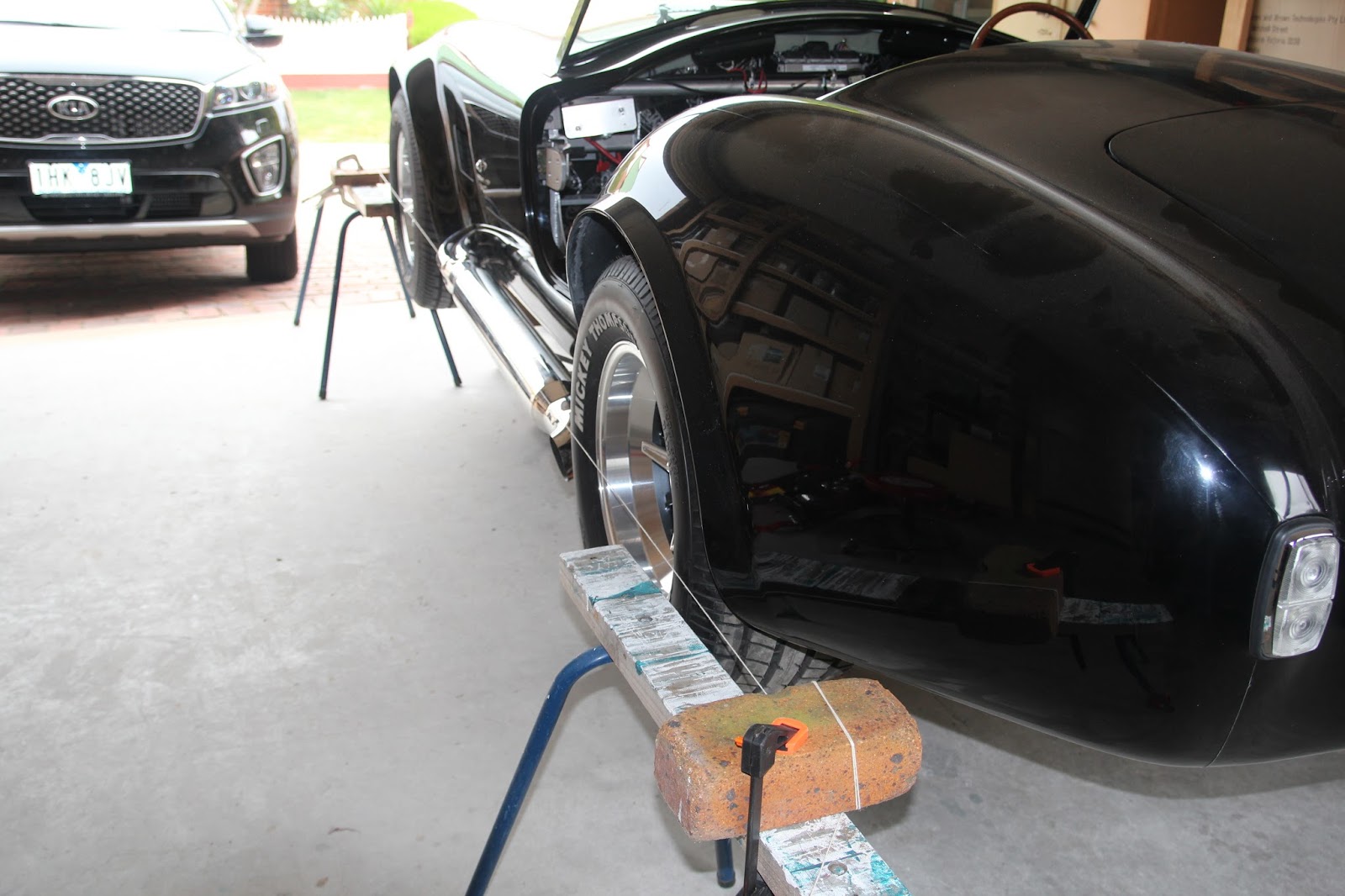
When setting the line, I positioned it 1mm from any point of contact to avoid distorting the line. That is 1mm from the front and rear tyres. As I adjusted the toe in/toe out, I continually tapped the the line closer to the tyre as I went. If I was working on the back tyre, I would get the tyre parallel to the string and maintain the 1mm gap then do the same to the front tyre until I had it right then locked up the adjusting rods. It is a very simple way af aligning the wheels but is by no means a substitute for a proper alignment, purely a means of being able to drive the car without scrubbing tyres.

After the alignment, the car was lowered to the ground. I had initially set the push rods with the rod ends making full penetration into the push rods making sure that both ends were firmly seated. The reason for this is that the push rod has a right hand thread on one end and a left hand thread on the other. By starting with the push rod in it's shortest state allows for maximum adjustment and both rod ends still remain equal distance on both ends. Also with the push rods in the short configuration. it is easy to wind the rod ends out which extends the push rod length and raises the car.

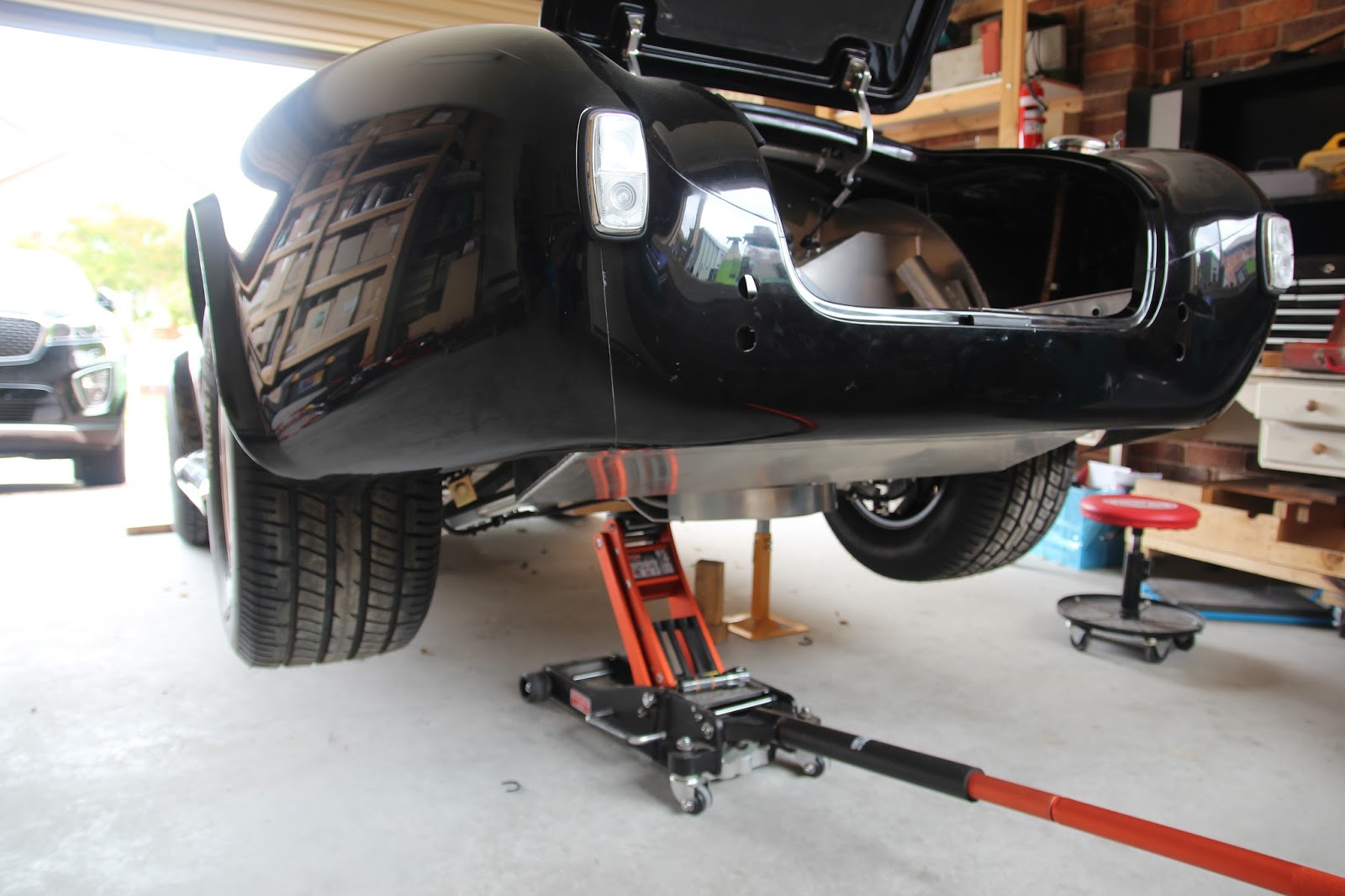
The down side to all this is the car came to rest on the jack which is a low profile unit so I had to block up the wheels with a piece 50mm timber. Once the jack was out I just jacked under the side on the recommended jacking points and pulled the blocks out and sat the car on the ground.

With the Cobra on the ground and a few minutes admiring the way it looked, I went around the car measuring from the floor to the lip on the mud guard and calculating the adjustments that needed to be made, I raised the car and made the predetermined pushrod adjustments. When adjusting the rods to lift the height of the car, the rods are easily turned by hand, not so easy to lower the car so hence winding the rod ends right in to start with. Don't forgt the lock nuts.

With my limited space in the garage, I put the Cobra on a set of car dolly's so I can move it around at will and also get my own car in the garage as well.

The upholstery is currently being done so when the dash comes back, we are off to the electrician again for final wiring and hopefully an engine start.

Until something else happens

Cheers

Russell

Tuesday 15 November 2016

Side Pipes Setup.

With the catalytic converters fully welded and in place, it is time to do the final set up of the side pipes. At this stage, the pipes can be adjusted up and down where they come through the body and the gap between the pipes and body can be set. The gap between the pipes and body is initially adjusted by cutting the pipes to length. As I said in the previous post, the flange plate was a tight fit to the pipes so that made the adjustment easier. I might add that the adjustment of the amount of fall on the pipes can't be altered because that is governed by the flange plate on the cats merge collector and this is now fully welded. When I was confident that the pipes where right, I tacked the flange plates in position.

You will also notice a star shaped infill piece in the centre of the pipes. Without this, the exhaust gas would blow through gaps in the pipes. The way I made these was to take a piece of cardboard and place it over the area I needed to fill and taped with a hammer until it cut the form I required then just traced it onto a piece of 1.6mm mild steel sheet. After cutting the shape into a square, I just used a die grinder with a 1/2" rotary burr to cut the final shape until it was a tap fit in between the pipes

Once I was confident that all was as it should be, I set about making the hangers for the side pipes. This was particularly easy as the pipes, where I wanted to place the hanger was above the floor line so it was just a matter of an angle bracket running from the bottom of the pipe then forming a right angle and bolting to the inside of the under car exhaust tunnel.

As I don't have the capacity to make a right angle bracket (no engineers vice, only a woodworking one) I picked up a pair of 40mm x 5mm x200mm x 200mm shelf brackets from Mitre 10 and cut it to suit. The off cut formed the brace so it worked perfectly. The rubber donut insulator started life as a heavy duty door stopper where I just sliced 2 x 10mm sections through the base and using a hole punch, increased the hole to 7/16"

I was happy everything was right so I paid another visit to my friendly welding shop and the job was complete.

I had the pipes welded to the flanges on both side as the flanges were at and angle to the pipes so I needed as much grip as I could get. The welder did a mighty job and the dressing on the flange sealing faces was very minimal. This is haw they look in their finished state.

When I have the car going and am happy that all is legal. I will be having the entire exhaust system fine grit blasted and ceramic coated in a satin black or dark aluminium to reduce the heat. The additional holes in the shelf brackets will be filled with JB Weld at the ceramic coating process so that will cleann them up nicely. The price label will also be removed (look closely at the mounted bracket and you will see it.

My next post will be on getting the Cobra on the ground.

Cheers

Russell

Monday 14 November 2016

Time For The Exhaust System

Working out the exhaust system was interesting to say the least. Pace supplied the headers but from the headers forward required the fitting of Catalytic Converters then exiting through some form of muffler. I chose to go the live side pipe route because I like the sound they make and they look good. I struggled for a long time with live side pipes or non active ones as the hazards of red hot pipes and children is always on your mind not to mention getting out of the car for driver and passenger can be an issue.

As Individually Constructed Vehicles are required to meet Australian Design Rules emissions testing, it required the use of Catalytic Converters rated at a minimum of Euro3 specifications. Trying to find cats that will fit the limited space I had to work with was a challenge. Their are plenty of cats that have lower 100 and 200 cell counts in a 4" diameter cat but I needed 400 cell in a 4" dia cat. It had to be no larger than 4" other wise it would not fit. Fortunately for me, a supplier I was talking to said he may be able to get me a pair of Euro4, 400 cell cats which he dug up from somewhere and he delivered well, not cheap but I was in no position
to argue.

I also had them supply 1-5/8" to 2-1/2" to 4 pipe and 1-7/8" to 3-1/2" to 4 pipe merge collectors while I designed mounting flanges for the merge collectors to the pipes and had them laser cut at a local engineering shop. Pace supplied flanges to match the headers. I also made the gaskets to suit the flanges


Before the cats can be routed through the gap I had to have some idea of where the side pipes are going to sit and how far from the body they will be so I set up some boards on axle stands and presses them up against the under side of the car as I didn't want them hanging down. The side pipes had to be cut down so the correct length of the cats and merge collectors can be determined.

Once a rough idea of the length and angle of the cats is established it is only a matter of directing the angles and cutting the cats and merges at the right angle, sounds easy doesn't it but it ain't. Without going into blow by blow detail, their is a lot of small cuts on both the cats and merges taking care not to cut too much off as the cats on a pretty steep angle and it would be easy to make the cat too large for the merge

It is a bit of a trick getting the merges to point in the right direction so they line up with the opening in the body and have equal spacing around the pipes. After a lot om mucking around it was time to set up the side pipes. The cats are in the tacked up state at this stage. I wanted a more aggressive look so opted for the pipes to exit the body on as much angle as I could manage and you will notice the pipes fall away 30mm over their length. You can't see it here but they also slay out from the body 12mm but still remain inside the tyre line.

It's worth adding that the flanges are a very tight fit on the pipes and I was able to position the flanges on any angle to get the required look with out tacking. When I was happy all was sweet I took the cats to some gents who are a lot more competent with a TIG than me and they did a great job. I also drilled the holes for the O2 bungs and had them welded in.

In my next post I will show how the side pipes were mounted and the brackets used.

Until then,

Cheers
Russell.

Monday 7 November 2016

So Many Little Things To do

Prior to fitting the body I temporarily fitted the rear infill panels as I new these would have to be removed to fit the body. It also allowed me to set up the fuel filler hoses and return lines. Now the body is in place I re installed the infill panels and pop riveted them into position. As a not for the future, it is a good idea to use screws for the infill panels as you cant get the bottom nut on the tail lights unless you lift the panel and if you ever have to remove the tail light it becomes easy.

With the infill panels in place I then fitted the fuel cap. I like jobs like this as you can actually see that you are doing something

Setting up the fuel cap is quite easy by just setting the latch at 5 o'clock and drill through the base. Just remember that when you screw the flip top cap on you will be able to screw the cap further which is not a problem as with 6 holes it indexes every 60° so you will end up in the right spot.

In an earlier post I showed the mods required to adapt to the Pace tail light assembly. When it came time to fit the lights, I found that there was not enough clearance to allow for the configuration that Pace suggests for the globe holders.Just a slight change of angle on the infill panel will upset the clearance no end. What I chose to do was to rejig the globe holders so they would fit. The pics below show the changes.
The first pic is the suggested arrangement and the second is the modified version. This is very easy to do by simply cutting a leading edge on the opposite side. Looking into my other pics I actually rotates the globe holders quite a bit further on the right hand side to give the required clearance. See pic below.

Probably the worst job on this entire car was trying to fit the wind screen. Fitting the wind screen is the No. 1 job before removing the body when you have nothing in the way of drilling the holes in the correct location.. I did mine after the electrics had gone in and the body replaced and trying to drill holes with a drill with a right angle attachment and a 14" drill extension juggling between the ECU, mountains of wire and all sorts of boxes and things that only electrical people understand is not my idea of a good day in the garage.

Fortunately for me the screen turned out perfect so albeit, the job was a task, we got what we wanted.

I made a bit of a blue when fitting the bonnet catches as I thought they were left and right hand but the are both the same hand so I had to rejig the holes and made a right cock up of one of them.The first layout was right but I thought it was wrong.
I actually recreate material to be able to fix up the mistake I made and it will require some paint but you live and you learn.

The boot catch was straight forward as the boot has an impression to align the boot catch. Just make sure you drill at the right angle to the boot lid and you will be okay. See above pics.

Went to fit the tail shaft and alas, it was 50mm too long so Pace ok,d the mods here in Geelong with a very reputable tail shaft builder. Works a
treat now. I have removed the tailshaft to allow the electrician the space to put the special reverse lock out plugs on the trans.

I have been busy constructing the exhaust system for my car. Pace provided the headers but from the headers to the side pipes was my responsibility so in my next post I can show you how I went about integrating the catalytic converters into the system then out to the working side pipes.

Cheers

Russell