Wednesday 23 December 2015

Filling Up The Engine Bay.

Having got the air intake filter and the MAF system sorted, I went back to a previous job that was presenting a small challenge.

The fresh air into the cockpit is fed via a 75mm flexible hose that runs from the front extension panel, up and over the front suspension and into the foot wells joining into the sliding vent. The problem I had with this is the misalignment between the entry hole and the sliding vent attachment. The entry point of the hose was about 25mm forward of the sliding vent making the fit impossible however, the stainless steel heat shield had a fair amount of discrepancy with the chassis but in the right direction allowing me to gring out the chassis hole for better alignment with out touching the polished stainless steel heat shield.

Although I only ground out 10mm, it was enough to allow the flexible tube to conform with the vent and slide over the port.I could then do a temporary fit of the flexible hoses.

Fitting the header tank and over flow tank was a never ending pain because I could not get the bits I wanted and when bits did arrive, they didn't even come close to fitting. There was a change in design mid flight and I was told they had a wizz bang upgrade but after months of waiting and some quite terse words I ended up with something I am not happy with and will be one of quite a few things that will be changed as at a later date. The problem I had was mounting the tanks on the front of the block. Problem 1) the mounting plate fouled the throttle body, 2) the mounting holes that were in the plate did not align with mounting holes in the block due to different casting configerations, 3) the bottles are squashed so tight together that getting a rubber insulation strap between the clamps and tanks is very tight, 4) they look wrong. All that aside, I was able to modify the mounting plate and drill and tap new mounting holes and this will suffice until I get it going.
.

Once the bracket was modified and bolted in place, the tanks were fitted then it was just a matter of plumbing them.

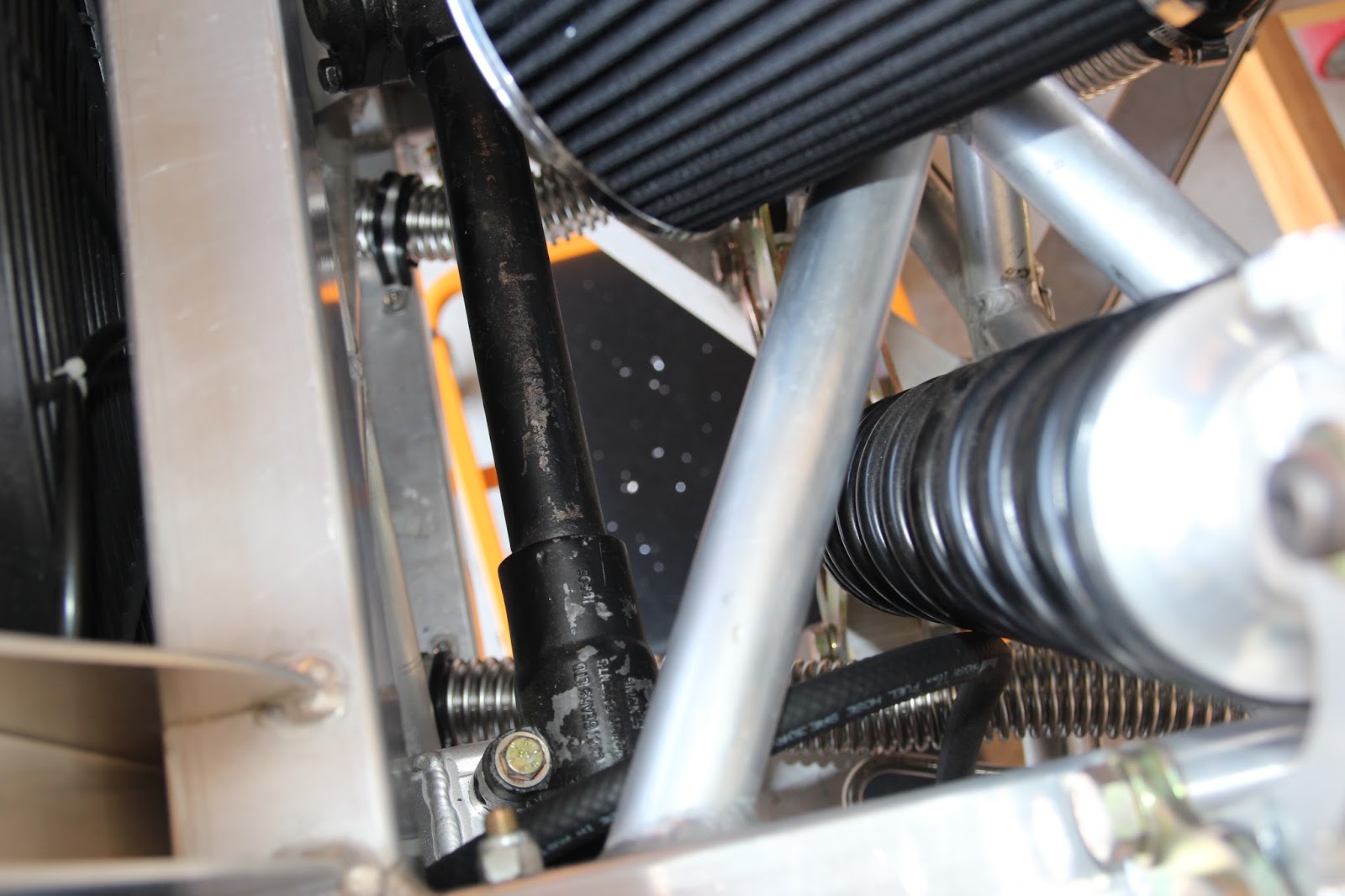
The radiator hook up was the next job to be done. This was a fairly simple job utilizing flexible stainless steel tubing and silicon joiners and bends. Getting to the radiator in situ is out of the question so all mounting bolts and bushes need to be removed to allow the radiator to tilt back far enough to get at the inlet and outlet tube integral to the radiator. Working the flexible tube around the chassis was quite easy and with the silicon joiners made the task straight forward. The only small issue was removing the thermostat housing and filing the inlet port down to allow the silicon joiner to fit and clamp in place. The inlet port had quite large protrusions in the moulding so with these removed it left a barb to clamp the joiner to.

I was not impressed with the general hook up of the cooling system although the system would suffice, I will be changing the complete system from the radiator connection to the engine connection as a winter project once I get this thing going but here is the finished item.

Well, thats it till next time when we fit the catch can and reroute the heater hoses as I will not be running a heater. Waiting for proper Quick Connect fitting to arrive from the good old US of A.

Cheers

Russell

Wednesday 18 November 2015

Some More Bits Added

I have pondered for sometime how to go about setting up the cold air intake and MAF sensor. It has been one of those dilemmas that ulimately sorts itself out in the long run. One of the issues was space , as it always is so I had to devise a system that would tuck itself down into the cross member and clear the bonnet. A friend gave me a system which had a 100mm diameter curved tube with a large 9" filter and 100mm rubber tubing connector which was too big for what I had in mind with the throttle body being 90mm so I went and bought a 90mm aluminium tube from Proflow and a filter from Auto Barn then proceeded to cut the rubber bellows section from the Ford Racing Cold Air Box that had been supplied with the engine management system. I made up the new air intake system and to say I was less than pleased is an understatement.

With my disappointment in this system, I revisited the 100mm system my mate had given me and why I did not see it previously I don't know but I noticed a weld on the tube and after pulling the system apart I see that the 100mm tube had been reduced to 90mm, exactly what I wanted. To make this tube fit, all I needed to do was to graft the MAF sensor which I had cut from the original Ford Racing Cold Air Box into the tube and away we go.

I was quite impressed with this as it gave me the clearance that I needed and with the bracket I made to support it, the air intake was quite flexible and should with stand any movement of the system.

I am quite anxious for the header tank and I want to get it fitted so I can get fully wired and start the car.

Cheers

Russell

Sunday 15 November 2015

Back To The Future.

Well, I'm not sure if this post is going forward or backwards, but some time ago I acquired a really smart three chamber billet aluminium brake and clutch fluid reservoir that I fitted to my Cobra and was so proud of the finished result. Not long after I had posted about this I received an email from someone who was reading my blog questioning the size of the reservoir and if it would suffice for the relatively large braking system I was using. The emailer sounded as if he new what he was talking about so a phone call to a friend and I was assured that the reservoirs were ok for what I was doing. I emailed back to this gentleman my findings and no more was said...that is until the engineer started his inspections. Well, the long and the short of all this is that the emailer was right, the reservoir is too small. I was supposed to have 90ml of fluid in the reservoir including the feed hoses and for memory I had around 84ml which was enough to put the stoppers on this. All sorts of things go through your head such as to put the original plastic ones on for registration then change back or kiss the $300 that it cost goodbye and do it properly. I chose to redo the system and get it right. I now have 143ml capacity per chamber and the pain of the $300 has gone and maybe I can sell to someone with a smaller brake system.

Having the bigger reservoirs mean that I had to spread them out a bit further which reduced the clearance between the front reservoir and the chassis member and I couldn't get the front hose into position with the fittings that I had. I pulled the reservoirs complete with mounting plate off the car and run down to the company that supplied the fittings and after a quick rat around we had the correct 45° fitting. You will notice this fitting in the above pic.

Once the reservoirs were in I ran the hoses down to the master cylinders and checked the alignment making sure that there were no areas of the hoses fouling up. I made up a simple bracket to separate the hoses out of 30mm x 1mm aluminium angle with three grommets for the hoses and it just works and looks a treat. I would like to say that I developed the bracket but a good friend made one to suit his car and I just copied it, we call it the Darryl Bracket and it has become quite popular with builders, now I'm not saying that he never swiped it from somewhere else but he gets the credit. I am going to put a similar separator up at the top so the hoses don't rub on each other. There is no contact with metal anywhere.

It was time to put the dash together as I had all the bits including the dash fascia and gauges. The dash fascia was made from 3mm moulded plastic and came with the dash impression in a large sheet of high impact plastic which I cut out using a band saw and coping saw for the tight areas. While a lot of filing and shaping was required it came up very well.

Setting the dash up in the correct position is a bit of a trick and not having the body on the car leaves it up to a bit of guess work. First thing to do was to fit the adjustable brackets that will hold the ends of the dash and fit them at an angle facing the driver.

Having placed the brackets in the appropriate place (some guess work required) the hole for the steering column had to be drilled and the question is, just where do you drill it. I aligned the dash central to the brackets and scribed a line directly up from the column

The scribed line being central with the brackets is obviously the place to start. There is quite a bit of vertical adjustment in the steering column but no lateral adjustment so if the centre line is correct, based on the brackets you have a good chance of bunging the column hole in the right spot. I decided to drill a 40mm hole that would exit marginally above the folded area at the bottom of the dash and go from there.

Once the column hole is drilled and the dash fitted over the column, you have a good idea as to where to go next. I found that to allow the indicator stalk to sit into the dash and to also lower the dash, I had to provide a 70mm hole so using the bottom of the existing 40mm hole I just moved the hole centre up an additional 15mm and drilled the 70mm hole. I used a special tool for this which you will see in the pics. An aluminium backing template is provides with the dash to allow easy marking of the gauge holes so it is only a matter of aligning the column hole and the rest is straight forward.

Next thing to do was to glue the template to the dash panel using many clamps

Now fit the gauges to the dash and the dash to the car and clamp in place.

Not a lot I can do with the dash now until the body is fitted and aligned.

So till next time.

Cheers

Russell.